

Hand switch contact development diagrams appear on schematic drawings. They help the reader understand how the circuit behavior changes when the switch changes positions. It’s important to understand how to use them to avoid making wiring or logic errors when creating, modifying, or interpreting circuits.
There are two main elements that need to be included on a schematic diagram.
The first is the eschutcheon plate drawing. It shows a graphical picture of the switch’s operating face and each of its physical positions (with labels). It will denote what kind of mechanical action the handle performs, like maintained-position, spring-return to a default position, or even a combination of both. It may also show additional features, such as the shape of the handle or whether it contains a key lock. The picture below shows how these elements may appear on a schematic diagram:

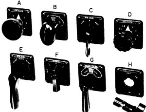
A photo of assorted eschutcheon plates is shown below, taken from the GE SB hand switch application guide:
HAND SWITCH CONTACT DEVELOPMENT CHARTS
The second critical element is the contact development chart.
The hand switch contact development chart communicates the behavior of each contact. It shows whether they are open or closed in each switch position. Closed contacts are usually marked with an “X” to indicate that the particular contact number closes when the switch is moved into the particular position. A basic chart is shown below:

We can see from this chart, for example, that contacts 2 and 4 are closed when the hand switch is moved into the “2” position. Contacts 1 and 3 are open in the “2” position. All contacts are open when the switch is in the “OFF” position. The eschutcheon plate diagram and contact development chart are usually shown side-by-side on a schematic diagram, like this:

The actual contacts, when shown in the circuits on a schematic, typically have a number written off to their side. Each terminal of the contact is also labeled. This method is helpful when determining how a circuit is actually wired, or needs to be wired (i.e. when you need to show where specific wires connect). The picture below shows this:
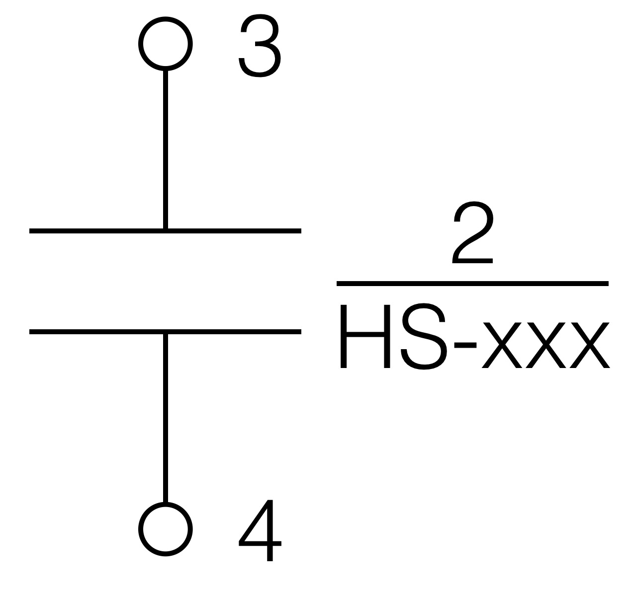
We see contact 2 of the hand switch, with its corresponding terminals which are labeled “3” and “4.”
The contact development chart can be more complex than what’s shown above. As the hand switch becomes more advanced, the chart increases accordingly.
For example, the contacts on the standard model may be break-before-make. On the chart shown above (from Figure 137), contact 2 will open before contact 1 closes when moving the switch into the “OPEN” position. But certain applications may be better suited for make-before-break contacts, which would mean that contact 1 closes before contact 2 opens when operating the switch. These are called overlapping contacts. This ensures continuity is maintained during the switching operation. To show this, the contact chart may add an intermediate column between two positions. Switches made by GE follow this notation. The overlapping contacts are shown in the chart below as asterisks (*):

The asterisks indicate an intermediate position that you can’t detect when turning the switch, but which do exist in order to ensure the contacts maintain continuity during the transition. Consider contacts 1 and 2. In the “OFF” position, contact 1 is closed and contact 2 is open. When switching from the “OFF” position to position “1,” contact 2 closes in the intermediate position before contact 1 opens. In other words, contact 2 makes before contact 1 breaks.
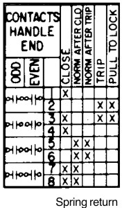
Standard mechanical hand switches use rotary cams to operate the contacts when the handle rotates left or right. These switches can be made more complex by adding lateral action contacts that open or close when the switch handle is pulled out or pushed in. As the degrees of handle motion increase, so does the contact development chart’s complexity. The chart below shows a spring-return-to-normal switch with more complex features, such as contact states which vary depending on which position the switch returns to normal from:
CONCLUSION
Contact development diagrams and charts are basic features of schematic diagrams in circuits that use hand switches. They are helpful elements that pack a substantial amount of information into a compact format. Because of that, they can be difficult to read at first, especially if it’s your first time encountering one.
Understanding the basic switch aspects makes it easier to understand more complex diagrams. It is also important to understand the mechanical characteristics of the switch because they directly correspond to the electrical characteristics.
One thought on “Hand Switch Contact Development”